Obligatory Background History…
Years ago I developed an interest in designing electronics and, at the time, sought to actively pursue this interest with the intent to parlay the desire into some manner of lucrative profession. As a starting point, I began tinkering with some unwanted gear I had laying about the house. One of the first thoughts I had was to alter the existing circuitry of an old Arion octave pedal that had been collecting dust on a shelf for years. Being woefully unaware of how circuits worked I thought “Hell, I’ll just break off this colored cylindrical doodad and this black roundy thing and see what happens.” Of course the result was that the pedal immediately stopped functioning, but a seed had been planted that years later would come to fruition.
Fast forward 3 years when a friend sent me a link to an article on “circuit bending”. Having educated myself a little more on the basics of electronics (going so far as to enroll in a technical school and then promptly drop out once I realized that designing electronics involved that most dreaded of topics: math), I felt a little more comfortable cracking open some old keyboards and having a go at this fascinating process. My first few attempts were boring failures and the lack of instant gratification prevented me from diligently pursuing the issue further.
Then, in the spring of 2004 I was booking performers for an ambient event in my region when I met a young woman by the name of Khate, a prolific circuit bender. Inspired by her exploits, and the fantastic creations of her equally talented boyfriend Wayne, I decided to have one last go at this circuit bending thing. So one boring, winter morning I cracked open an Ibanez AutoWah that I’d had for ages and started prodding the board with a piece of wire. The resulting finds would become the CBAW “Bruiser” and would trigger an unquenchable urge to conquer the art of circuit bending pedals. The rest is, as they say, history.
Tools of the Trade
There’s no “right” or “wrong” way to circuit bend a stompbox. My methods are always evolving, but some of the basics have proven to be invaluable over the years. Pedals have two disadvantages that make them generally undesirable bending artifacts — they lack internal monitoring (no speakers) and they generally require some sort of breakout box to house the switches (no space). Because of this the basic toolkit for bending a pedal is slightly different than that of bending the average keyboard or a toy.

The basic tools.
Any circuit bending project is going to have some basic tools: a set of different colored markers for noting your finds on the circuit board (Sharpies work great), wire stripper for making a probe wire, probe wire (I alternate between a long stranded wire and a short piece of solid wire, depending on my mood) for probing the board, a screwdriver to take the housing apart, some short bits of wire with alligator clips on each end (something that I’ve just started using) to make testing bends with switches and pots an easier task, and if you want to get involved some variable resistors in a variety of ratings.
Some other tools that I use when bending pedals are my trusty RT-123 drum machine to input a signal into the pedal, headphones to monitor the output of the pedal (just a warning, I normally rest mine on my shoulders, around the neck, because some bends can be LOUD), a patch cable to connect the drum machine to the pedal, and some water to keep the mouth moist and the head clear.
Getting Down to Business

If you’re going to be bending a pedal, you’re going to need a pedal to bend. I know this seems obvious, but I don’t want to overlook anything here. For this article I’m going to use a Boss Octave pedal that I had on my list of things to bend. I’ve read that this pedal is notoriously finicky and doesn’t have a long lifespan after being bent. I’m anxious to see if that is the case for me as well.
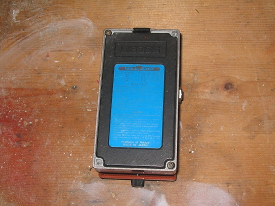
OK. So back to stating the obvious, the first step is to flip the pedal over and take off the bottom (I like to call it the foot plate, just because). This particular pedal is a blue label Japanese Boss, which means something to a small group of Boss fanatics.
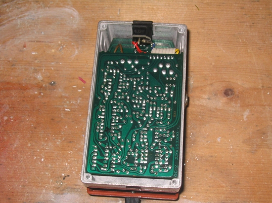
Once we get the foot plate off we see the sexy undercarriage of the circuit board. This is where all the action takes place. I typically turn the board over and familiarize myself with the locations of the IC chips and area where the power supply connects to the circuit board. As a rule of thumb you want to avoid the power supply and immediate vicinity. It’s very unlikely that you’ll find anything of merit there and the chances that you’ll fry your board are far greater the longer you poke around in that area.

Boss power supply.
While it’s not advisable to probe the power supply one of the fun things you can try is a voltage starve. Quite possibly the best thing about Boss pedals (in terms of circuit bending, that is) is the fact that power supply isn’t integrated onto the board like most pedals. The wire from the battery actually runs to the DC input jack and another wire runs from there to the board, which means you can add a pot inline that will work to starve the voltage on both battery power and DC power. Brilliant!

Being a huge fan of the voltage starve, its typically the first thing I try on a project. Here you can see how effective those alligator clip patch wires are for testing. One thing to keep in mind when working with a voltage starve is that the diminished power supply will affect how your other bent effects sound. Some bends simply won’t work when the voltage is starved. Others will improve. It’s best to test your bends with and without full power if you’re employing a voltage starve.

Once I’d settled on the pot value that I wanted to use for this I broke out my probe wire and went to town. There’s really no cut-and-dry method for this. The only advice is be thorough and clearly note your findings. When I find a two points that make a nice sound I’ll generally mark them with a unique color and if one of those points happens to work with other points on the board, I’ll mark that one with an “X” to indicate that it is the Point Of Origin, or lead, for that color group. If I find that a particular point works well with a pot, I’ll make a little resistor squiggly mark on the board next to that point. Some people keep detailed notes in a notebook. I won’t pass judgement since some of those people produce amazing results that I can’t replicate, but I’m far too distracted for that much detail. The best advice is to find what works best for you and stick with it.
At this point the pedal is ready for the real fun. But I haven’t gotten to that point yet, so this article will pick up again when I get to wiring and the breakout box. Much of this is covered in the Building the Mutant Phaser tutorial, but this project is going to involve something special that won’t be revealed until the project is finished.
Until then, etc. etc.
What ended up happening with your OC-2? I just started pedal bending in the last couple of weeks. I did a pretty straight up copy of Noisedom’s OC-2 synth mod [ http://www.youtube.com/watch?v=up5SKmEOZeI ]. Sounds amazing now. Did your OC-2’s “notorious finickiness” take it out on you?
To be completely honest – I don’t quite remember. I think this was the pedal for which I designed an elaborate RCA patch-bay breakout box that was ultimately recycled for an SK-1. I don’t think the pedal itself died on me. I think it was more a matter of a shift in priorities.
But, I could be wrong. This tutorial is close to five years old and I’ve long since sold all the gear I bent back then.
if I wanted to take an effects pedal and circuit bend it so it makes noises etc to be used for my power electronics project how would I do so?
lol come one now , you burned it up, i build pedals and know that you start feeding to much signal into the wrong ic pin and youll easily kill it