Building your own CBSP Mutant Phaser isn’t as difficult as it sounds. Since I started bending pedals people have asked me to bend various different pedals for them, and the one model that has been most popular, by far, has been the CBSP Mutant Phaser. This deviant audio artifact is derived from a rather innocuous Arion Stereo Phaser and is outfitted with 17 bent effects ranging from harsh distortion to ear-piercing modulation. I offer this tutorial as a guide to anyone interested in building their own Mutant Phaser. Keep in mind this is a detailed description of the methods that work best for me. Read it over, glean what information suits you best and experiment with it.
The Arion Stereo Phaser bending schematic.
Getting Started
First thing we’ll need to get this party started is that which will be bent – particularly the Arion Stereo Phaser. These can be found extremely inexpensively at many online retailers, or on eBay. (Update: These pedals have been discontinued and are becoming increasingly rare to find. I recommend snatching up a few, now, while you still have the chance.)
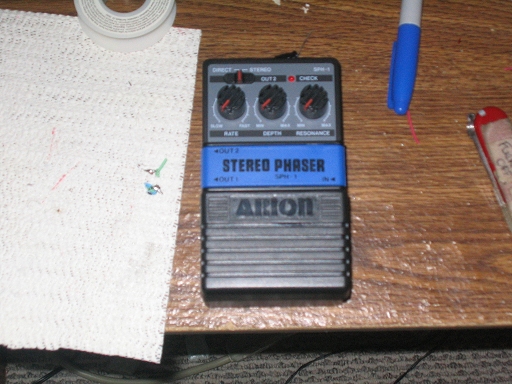
An innocent, clean Arion phaser.
We can’t do much harm staring at the top of the unit, so let’s flip it over and remove the four screws on the bottom. Note that one of the screws is shorter than the other three. When we get around to mounting the pedal later, you’ll want to make sure that screw goes back into the hole from whence it came. Once the screws are out, remove the metal foot plate and the black plastic sheath underneath, exposing the circuit board. Hang on to these parts for right now.
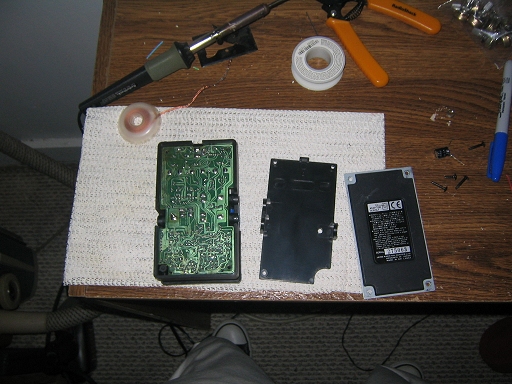
If you’re going to probe out your own findings, now is the time to do so. If you want to make a cookie-cutter model like the ones available for purchase, you can use the “schematic” found on the Bent Pedals site.
Preparing the Enclosure
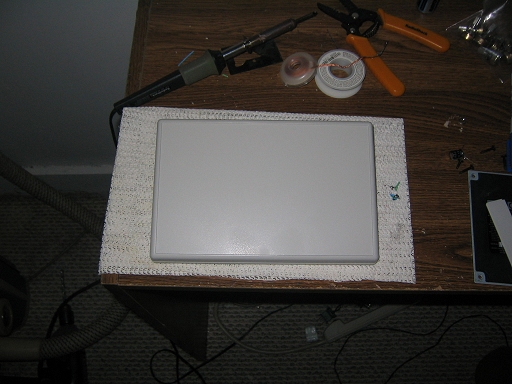
For (almost) all of my bent pedals I use Hammond ABS enclosures. I find that they are inexpensive, easily tooled and extremely durable for tabletop applications.
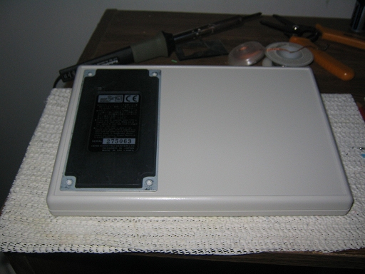
On the back of the enclosure you’ll see two removable panels, which make for a perfect measuring tool when laying out for the switches.

Panels on the backside.
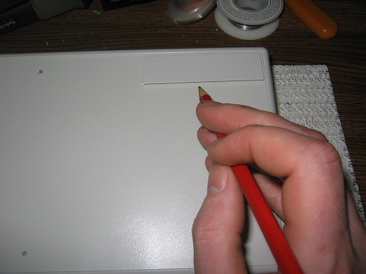
First thing we’ll do is pull out the foot plate we took off the bottom of the pedal earlier (I told you to hang on to it…), and align it on the left side of the enclosure. If you’ve bought the same size enclosure that I have, you’ll see that there’s about a centimeter gap between the top and bottom of the plate, and the top and bottom lip of the enclosure. Match this distance between the left side of the plate and the left side of the enclosure. This should give you the proper placing for the pedal. Be careful to keep it as even as possible, or your pedal may not mount correctly. Once you have the plate in place mark where the holes are located. You may want to go ahead and drill the holes now, to make sure that they line up properly. I use a 7/64 inch drill bit and it works like a charm (sorry, don’t have a metric equivalent). After the next step you can throw away the foot plate if you feel so inclined.
After we have marked where the pedal will be mounted, we can start laying out for the switches. Place one of the panels we removed from the back, two steps ago, against the top lip of the enclosure and strike a mark along the bottom of the panel. Use a straight edge (the foot plate works great for this) to carry the mark out across the face of the enclosure. Next repeat this process aligning the top of the panel with the line you just marked. The last horizontal line will be made by aligning the bottom of the panel with the bottom lip of the enclosure.
For the vertical lines we’ll use the panel again, this time turning it on its side and aligning the right edge with the right lip of the enclosure. Strike a mark along the left edge of the panel and extend upwards with your straight edge. Repeat this process four more times, using the previous mark as your alignment for the right edge of the panel.

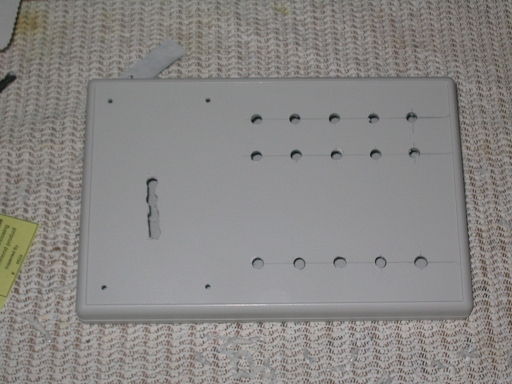
When you’re finished you should have something that looks like this.
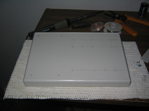
Marked and ready for drilling.
Normally I drill pilot holes with a 1/16 inch drill bit. This helps keep the holes lined up and makes drilling bigger holes easier. As you’ll see later in the tutorial, even with the marks and pilot holes I’m no good at drilling in a straight line. Regardless of the pilot holes, we still have to drill for the switches. The toggle switches I use require a 1/4 inch hole, therefore I recommend a 1/4 inch drill bit. The pots are slightly larger, but I just use the same bit and wallow out the hole a tad. You can do the same or find a bit better suited for the task. I won’t pass judgement on you…
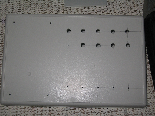
When the holes for the switches are complete, you’ll want to drill a few holes under the area where the pedal will mount, to allow for the wires to pass through. I typically drill four holes close together and use a knife to cut out the excess plastic.
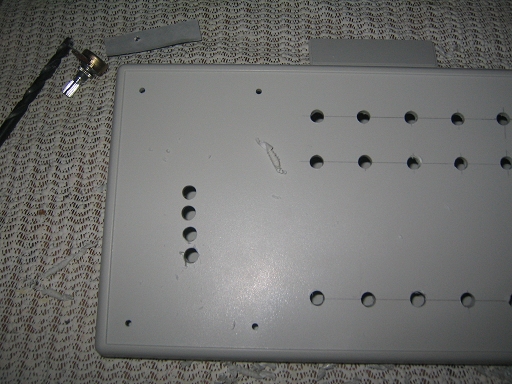
Now’s a good time to open the enclosure up and clean up the burrs around your holes. I also remove the mounting brackets on the inside (highlighted in blue), as they can impede the switch mounting later.
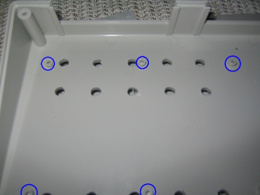
Get rid of these.
All said and done you should have something that looks a little bit like this. This is the point where we decide if this thing wants for a paint job, or not. If so, it’s out to the paint booth for a heinous assault with the spraypaint cans. A few things to keep in mind: you’re painting ABS, so use a plastic primer first. I learned this lesson the hard way by having paint peel off when I was mounting switches (sorry Devi!). Allow adequate time for the paint to dry before handling. If possible CLEAR COAT. You’re likely going to be lugging this thing everywhere*, so protect your paint job with a few layers of clear coat.
*Work, gigs, bar mitzvahs, funerals … I mean EVERYWHERE.
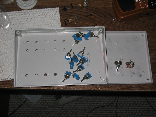
Installing the Switches
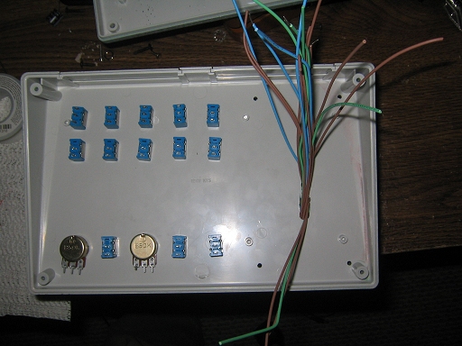
This section is the easiest. We’re simply mounting the switches in the holes we’ve drilled. I generally use SPST toggles, center-off SPDT toggles and potentiometers.
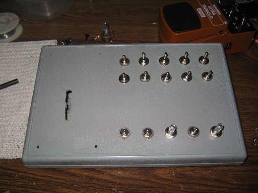
Merely pop the switch in place, throw on the washer and clamp down the nut. With the SPST toggles you’ll want to make sure that all your poles line up on the bottom (you’ll see what I’m talking about when you look inside) so that the “Off” position is the same for each toggle. When you’re done it may look like this.
Wiring Your Mutant Phaser
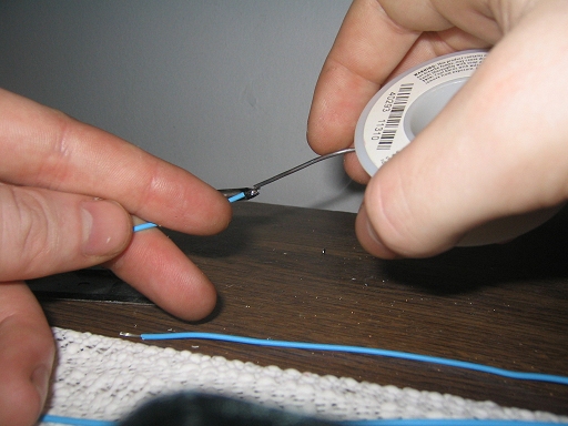
When doing any circuit bending I always tin the wires I intend to solder to the circuit board. This allows me to make exceptionally fast and surgical wire additions to the circuit board without the risk of overheating any components. First cut a length of wire about 7 inches long and strip back about 1/4 inch of the plastic insulation.

Then tin the wire by placing it on the tip of the soldering iron for a second and applying the solder.
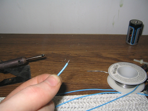
Next we trim the freshly tinned wire down to about an 1/8 of an inch. This gives us a wire that is quickly and easily soldered and won’t have a lead so long that it interferes with mounting the pedal to the enclosure. If the lead is too long it can put pressure on the solder joint causing the bend to malfunction. Granted this may seem like a cool idea, but not when it renders the entire pedal unusable (as has happened to me once).
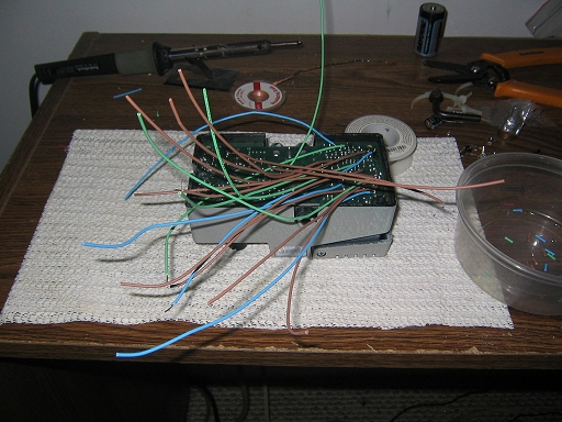
Now that we have tinning down, we can start attaching wires to the board. For each group of common points I’ll use the same color wire. To make my life easier I’ll strip and tin just one end of the wire for all the bending points, and strip both ends of the wire for the common Point Of Origin. This way I can easily identify which wires go where after the pedal is mounted and I can no longer see the circuit board. If I have special needs for specific points (such as potentiometers or additional resistors or capacitors) I’ll mark the loose end of the wire so I can find it later. When you’re finished soldering all the wires to the board you’ll end up with a multicolored electronic porcupine that looks something like this.
Then we slowly and with great care feed the wires through the hole we cut for them in the enclosure. Be mindful of all your wires, making sure they all get through the hole and that you don’t tug any of them needlessly. After you get the wires fed through the hole, you can mount the pedal to the enclosure using the screws you removed from the pedal way back in step one. Remember that short screw. If you lucked out you will be able to mount all four screws, but if not you may have drilled a hole through the screw post on the enclosure. As long as you get at least opposite corners screwed down tight, you shouldn’t have any problems.
Wiring the switches is relatively easy, albeit time consuming. The most intensive part of the process is wiring the switches to the pots. To do this simply take the wire from the appropriate bend point (a blue wire in this diagram) and wire it to the top pole of the SPST switch. Run a short wire from the bottom pole of the SPST switch to either end lug of the pot (the lug you choose will determine the direction you must turn the knob to achieve full effect, if you’re unsure about this, experiment before you solder). From the center lug of the pot, solder a short patch wire that will be used to connect to the common point of origin for that bend. Repeat this for both pots.
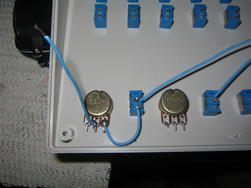
Wiring the pots.
After both pots are wired, twist the patch wires together with any other wires for that common group. Then twist in the Point Of Origin wire (the one from before, with both ends stripped) and drop a few beads of solder on the bunch to keep them from untwisting. As an added precaution I also wrap the connection up in a little black electrical tape. This will insulate the connection as well as help prevent the wires from being pulled apart.
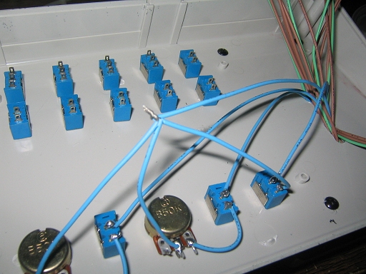
Common points all connected to complete the circuit.
The process for wiring the rest of the switches is much easier. The bending point always goes to the outside pole of the switch. If you should get into the groove and suddenly realize that a few of your wires aren’t long enough to reach the switches, don’t panic. This happens to me more times than I care to admit.

The easiest way to remedy this is to cut another piece of wire long enough to bridge the gap between the existing wire and the switch. Strip the ends and twist them together. Add a bead of solder to lock the joint and wrap with black tape.

In the end the patchwork will hardly be noticable (or so I’ve always hoped).

After all the bending points are wired up we need to start completing circuits by wiring up the common Point Of Origin for each group. We start by stubbing up little patch wires from each switch of a particular group, keeping in mind that they must all be wired together and must all be wired to the common point wire coming from the circuit board (ie, the stub wires should be long enough to accomplish this task).
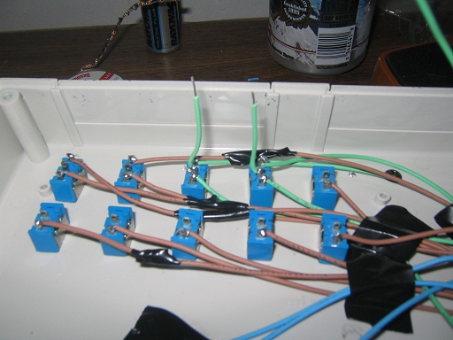
POO wire stubs.
Once all the switches have been wired for the common Point Of Origin, twist all the stub wires together and twist in the common wire from the circuit board. Add a bead or two (or three) of solder and wrap in black tape.
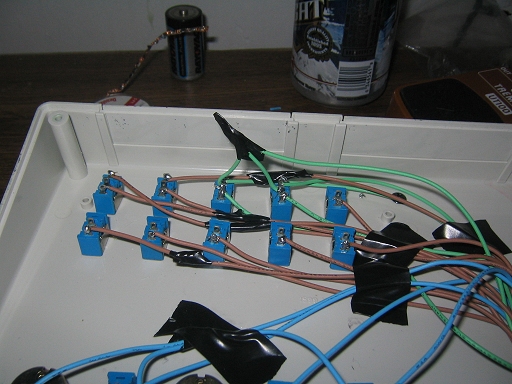
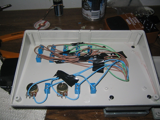
Repeat this process for all your switches and all your common point groups. I tend to tape down sets of wires as I finish to keep everything neat and out-of-the-way. Regardless, when you’re finished it should look a little like this.
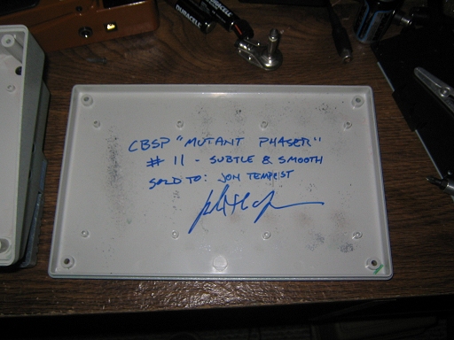
Only thing left is to sign it and put it back together.
You are now the proud owner of your very own CBSP Mutant Phaser. Treat it with respect and it will never let you down. Carry it with you everywhere you go and be the envy of your friends and peers alike.
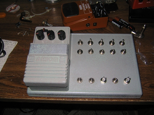
Go forth, young one, and besmirch the world with your sonic terror.
My thanks to Jon Tempest for being patient while I built this Mutant Phaser and documented the process.
Looks good, one suggestion though: ditch the electric tape and get some heatshrinks. They look cleaner, don’t leave your wires sticky and don’t peel off like electrical tape tends to after a year or so