The following tutorial was gleaned from the Tablebeast website, while it was still available; is presented for the sake of posterity and common knowledge; and is not the work of anyone affiliated with Intelligent Machinery, nor any of its imaginary subsidiaries.
Step 1: Inspection and Mental
Preparation

The first thing you want to do is inspect your Casio SK-1. Make
sure it works before you open it up. Even if it has worked in the past as far as
you know, throw some AA batteries in there and fire it up, check all the
functions and ensure that it is operating before you take it apart. Nothing
would be worse than working on this thing for hours only to put it back together
and have it not work at all. If it works perfectly before you started the mod
and you follow these simple instructions, it will work perfectly when you are
done, its that simple. Oh, yeah feel free to bite it and taste what quality
Japanese workmanship is like. (Click on any pics to enlarge them). Next, take a
deep breath and appreciate how clean the air is. Ventilate wherever you are
working and even turn a fan on low just to circulate the air where you are.
Solder is toxic and can lead to things like eating keyboards.
Step 2: Assembling the Tools and Parts

Ok, now get all the stuff you will need for the mod ready. Here is
your tool check list.
1. A soldering pencil, stand for holding it and sponge for cleaning it. 15 to 30 watts is fine, get the best you
can afford if you intend to do this sort of stuff for a while. I have pictured a
super cheap Radio Shack model that has a switch for 15 or 30 watts.
2. Wire cutters / strippers. Again I have a cheap Rat shack set pictured here. Its all you need. Like any tools though, you get what you pay for. If you are planning on doing this type of stuff a lot, get the best you can afford. It will serve you much better than the cheap stuff down the road.
3. Drill or cutting device. I use a Dremel with a sheet rock bit on it. Its designed to cut sheet rock and the like, but it works wonders on plastics (even Aluminum in a pinch). The right angle adapter makes working on this kid of stuff much easier. I used a cheap battery powered black and decker (or something) for a little while, but it died before too long. I bought the Dremel and never looked back. Anyway, anything that can make holes and cut a fairly straight line will do. I even used a pocket knife for a while, you can score repeatedly until it cuts through and twist in a circle for holes, just be careful.
4. A Sharpie. Don’t overlook this. You will need it for marking both on the case and the circuit board. Any permanent type with a small pointed tip will do.
5. Small phillips screwdriver. This is vital, you can’t even get the SK-1 open without it.
6. Solder, of the rosin core variety. You can’t connect anything without it. I recommend practicing at least a little if you’re a novice. Do this by taking any old piece of non functioning electronics plus some wire leads and practice soldering the leads to solder joints on it. solder and then once dry give a little tug to the wire, if it comes off you suck. Try again until you get reasonably good at it.
7. Safety Goggles (not pictured because I was already wearing them when taking the pics).
8. Additional items not necessary, but nice to have.. 5/16″ nut driver, zip ties, plastic friendly epoxy, pliers, small chisel, sponge, rosin, headphones, beer.
Here is your parts checklist:
1. 1x Unmodified Casio SK-1. Do I really need to explain why?
2. 2x 12 point RCA patch panels. I get these from RP Electronics in Canada,
you can get all the parts and tools you need for this project there as well,
INCLUDING the machine screws.Or you can use any 12 pt. RCA patch panel, or
modify this part of the project for yourself and create whatever kind of patch
bay you want, from banana plugs to a TT patch bay, internal or external, the sky
is the limit.
3. 4x SPST, SPDT, DPDT, DPDT C-OFF will all work, get what you can as I will show you how to wire up whatever you choose. The DPDT Center-off variety adds functionality and complexity to the helper section of the patch panel.
4. 1x 1/4″ socket, any kind will do.
5. About 40 ft. of wire. I buy new surplus 10′ 25 pin D-Sub cables, cut off the ends to use with my external mod boxes, and then cut 20″ lengths of what’s left, one for each SK-1.This wire is far superior for this type of project than just about anything you could buy, especially when weighed against cost. If you want you can even find and use just about any computer cable found at the thrift stores, dumpsters, attic, yard sales, boot sales, etc. and use it. Once you cut the end off, its fresh perfectly preserved wire inside. I used to do this plenty, but buying it new is actually a lot less trouble when you build as much stuff as I do. The only real rule is to keep the wire thin. 22 or 24 awg is best, thinner will work ok if you
are careful, but thicker will lead to problems for lack of room for the bundle.
6. 1x 10 ohm resistor. This is for the 1/4″ output to replace the load of the speaker, you could even put a capacitor on there for filtering as well, but I leave that up to you, I like all the background noise in places, so I just use external filtering.
Step 3: Prepping


Flip over your Sk-1 to expose the underside. Get your screwdriver
out and take out the 11 screws residing in the case. Place them in a cup or jar
otherwise you will lose them.


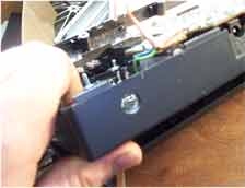
Open up the beast and flip the bottom of the case over. To make
everything easier for yourself, go ahead and clip the power leads from the
battery compartment to the circuit board. Be sure to leave enough of a tail on
the wire on the circuit board to ensure you remember which is red and which is
black and where it is. Matter of fact, go ahead and mark on the circuit board
with he sharpie R for red and B for black just in case. This will make the mod
go much easier, trust me I would know.
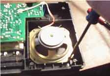
Take the four screws out off of the speaker, cut the leads, and
then do whatever you want with it: throw it away, make an array out of 50 of
them, put them in a toy car, choke on it, who cares. Just get rid of it, because
it is taking up valuable internal space.
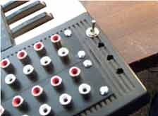
Step 4: Marking, Cutting, and Mounting


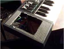
Put the two halves of the case back together and flip the unit
back over. Find the now vacant speaker compartment on the left of the unit as
pictured (pretty hard to miss). You can measure the space you will need without
the aid of a ruler, but if you must, go right ahead. from the edges of the
speaker channels, measure a 1/4″ in on both sides, this will center up the patch
panels. Now draw a line from the bottom of the top set of channels down to the
top of the seventh channel of the bottom section, as pictured. Now draw a line
with your sharpie connecting the two sides with a top and bottom line, following
these channels. I know it sounds confusing, but just look at the picture and it
will all be clear.


Before you drill be sure that you are not going to contact the
ground wires for the keys or the huge output capacitor with whatever you are
cutting with. Just drill barely as deep as you need to avoid destroying any of
the vital internal components. Be very careful, whatever you do. Now, cut this
section out, following the sharpie marks, and throw away the cut out piece.
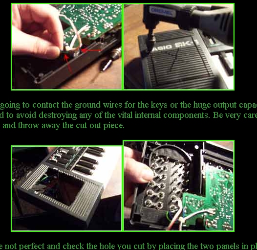
GO back and clean up any edges that are not perfect and check the
hole you cut by placing the two panels in place, making sure that none of the
parts interfere with each other. The panels should mount flat and neat. Trim any
excess interfering areas.


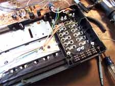
Now, you are going to line up the two patch panels in the cut out
space. I line them up by centering the pair and using the very edge of the
fourth channel to keep it straight. Drill one hole at a time and be sure to put
a screw through each hole as a placeholder as you drill. That way you can be
sure of the neatness of your layout. I usually go in diagonal order. From bottom
left to top right, then reverse for the adjacent panel, and finally filling in
the last four holes. That way if you make a mistake for placement you still have
a few other holes you can re drill. Just work slow and carefully on this part
whatever method you choose to use, as the quality of this will be the most
obvious part of the mod, make sure it looks good!


Secure the 3/4″, 6/32 Machine screws with matching nuts, you can
use a nut driver, pliers, vise-grip, whatever to do this.


Be careful with the top left corner here so as your mounting screw
does not interfere with the circuit-board or parts on it.To get the screw into
this tight place you can either take all of the screws out of the circuit board
and flop it over or put a nut on the tip of a small screwdriver and hold it in
place from above.
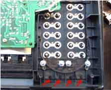

Now in the four areas below the speaker hole is where you will put
the helper section switches. Mark 1/4″ for each hole if mini style switches are
used. Center the holes up as shown in the left pic where the red arrows are and
be sure to trim any excess interfering plastic from the case as shown in the
middle pic. Test each hole with a switch, then when it is nice and snug, not
loose or too tight, secure each switch with the accompanying nut and a single
lock washer, as there is not really enough thread on most switches for both
washer and lock washer.


Measure about halfway between the two mounting screws a hole large
enough for your 1/4″ output jack. cut it where it will not interfere with your
new patchbay and you should be fine, just look at the pics for placement.


Looking good! Now, the cosmetic steps of this project are
completed from the basic standpoint. Here you could co on to paint, mark, lebel,
or do whatever you want to modify the unit visually. I don’t do anything because
I like the basic look, though I have done extensive decorating in the past. My
advice is do whatever you want with it, have fun. Make the mod as obvious or
stealh as you wish. Now onto the soldering.
Step 5: Soldering


The first thing you will do is remove the seven screws holding the
circuit board to the case. Place these in a jar or cup so that they do not get
lost. These screws are shorter than the main case screws, so they are easy to
spot the difference, use the same jar if you want then. Also remove the volume
slider and keep it with the screws so that it too does not turn up missing.

Flop the circuit board over and you are ready to rock. Note that
if you had difficulty getting one or more of the mounting screws on that this is
good time to do that, as you are unfettered with access tot he patch bay now.
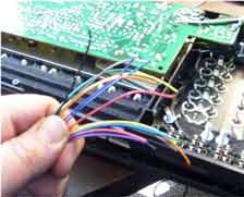

Take your 16 20″ lengths of wire and strip both ends of each. On
one end you should have a 1/4″ or more, fully tinned tip for soldering to the
patch bay and the other should have an 1/8″ tip for soldering to the circuit
board. Make you tips nice and solid with solder when tinning, that way there is
minimal heat transfer when soldering to the circuit board.


Work one wire at a time soldering all 16 to the patch bay end
first. Then bundle the wires with zip ties, run the wires under the circuit
board and around the other end. This will keep the wiring from interfering with
the keys or battery compartment, etc.
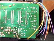
Replace the circuit board on the case and secure all seven
screws holding it to the case. Find the rear of the right most IC (furthest away
from the patch bay). From bottom left corner of the IC (where the mic and line
inputs are), counting clockwise from the bottom left, place a black dot adjacent
to pins 2, 3, 5, 6, 8, 11, 13, 14, 16, 18, 21,23, 24, 25, 26, and 28. Since I
use color coded wire, I will segregate them into two rainbow looms of 8 in the
same order as the resistor color code: black, brown, red, orange, yellow, green,
blue, purple. That makes all 16 wires for the patch bay, which I wire in the
same order, very easy. Refer to pictures for any questions concerning this.
Now, solder the 10 ohm resistor across the 1/4″ output from the
positive to negative lead. Also solder the white lead from the ex-speaker to the
ground or sleeve of the jack and the one with the red stripe to the positive or
tip lead on the 1/4″ jack.


Lastly we will hook up the wiring for the helper section. Now, you
can use different methods in the section from this simple 4 switches all
separate, to array in series, parallel, midi control, trigger control, etc.
Presented here is the simplest setup, it works very well. Basically just wire as
shown, pairs are set up in an under over fashion, just run the wires (8x about
3-4″ cut, stripped and tinned) so that the switches close the circuit between
these pairs.
Inspect the case for debris, dirt, solder drops, etc. Make sure it
is all clean, then strip the two leads from the battery compartment if you
disconnected it, re solder to the points they were cut from and close this
sucker up. Put in two screws just to hold it all together, and test it! Put in 5
fresh batteries and hook up headphones to the 1/8″ jack or a line out to the
1/4″ jack. If the headphones are in they will shut off the 1/4″ in the same way
it used to shut off the speaker since you are running off of this. Make sure all
of the normal functions still work and then you can commence placing patch
cables in the patch. Keep in mind that the top 16 sockets are the live part of
the patch connected to the SK-1 circuit board. The bottom 8 are connected to the switches at the bottom. Now you can use say 1 patch cable to connect socket 2 to socket 13 or you could use two cables, one to socket 2 and 1/2 of one helper section and the other cable to socket 13 and the other half of that helper section. Now the switch connected to that helper can turn the mod desired on and off. You have 4 pairs of these, so that you can set up and recall patches.
That’s about it, from here you have the infinite possibilities of the tablebeast
designed original patch bay SK-1 mod. Pretty sweet.
Hey could you tell me if these SK-1’s are ready for direct to amp plug-in? It has a 1/4″ hole for that it the back, right?